Sid A.; July 24th, 2020
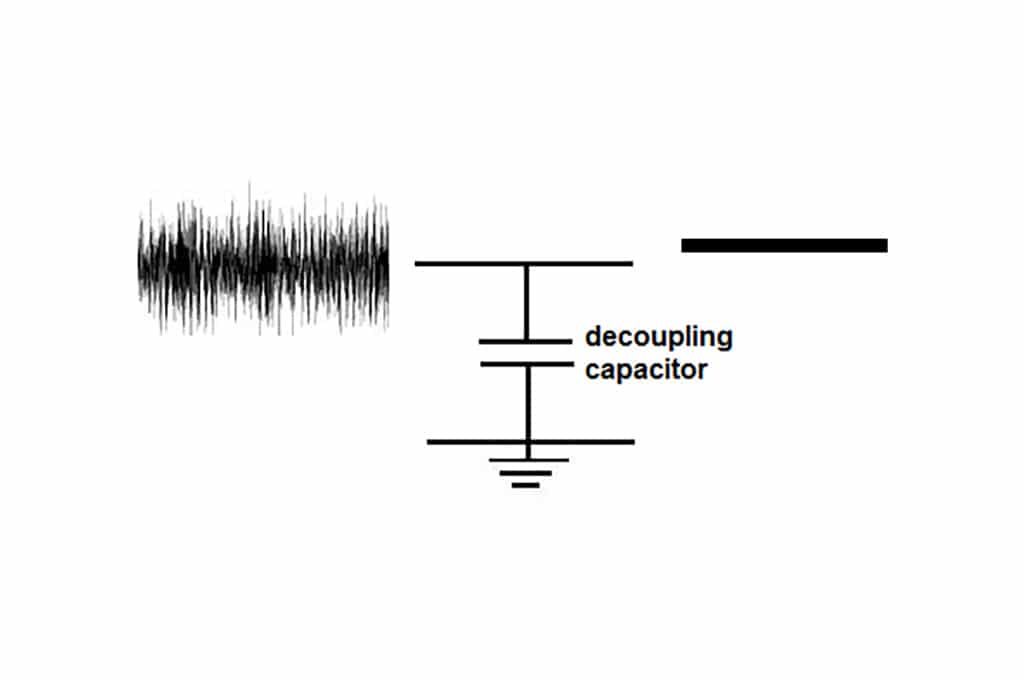
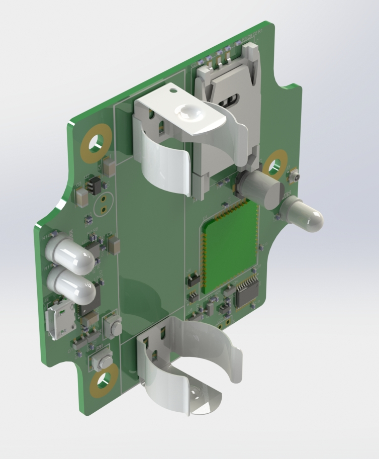
I recently finished up work on a board that involved cellular connectivity. The device served as a prototype for a water leak detector. It had a few sensors on it, a battery charger, USB programmer, and of course a cellular module. There were a couple problems with the first revision. But the trickiest one…it refused to connect to the network! I tried all sorts of things, switching the antenna out, different SIM cards, different locations, and a long list of AT commands. Nothing was working. While I was sending AT commands, after a certain period of time, the module would simply freeze and not respond unless I reset it. This was very strange. I had problems with the logic levels on the UART lines, but I thought that was fixed. I decided to check on the power supply. The first time I checked it, I didn’t notice anything. After banging my head against the wall for a few more days, I checked it again, more thoroughly. Lo and behold, there was a big dip in the supply voltage that corresponded to the module freezing! I pulled some pins up and powered the module from a bench-top power supply instead of the on-board low-dropout regulator (LDO, drops higher voltage to a lower one). I tried connecting again and voila, the board connected to the network. So what went wrong? Enter the “decoupling capacitor”:

A decoupling capacitor “decouples” a noisy input supply from the cleaner output supply. It also smooths out sudden energy demands. In the case of this board, I had put a 100uF aluminum electrolytic and 100nF cap, in parallel on the voltage input. The datasheet for the module recommends stacking a 100uF tantalum, 100nF, 100pF, and a 22pF. When the module connects to the network, it suddenly draws a large amount of current for transmission/reception processes. The decoupling capacitors smooth out this demand. However the interaction between an LDO and decoupling capacitors on the output are more nuanced. Capacitors come with an “equivalent series resistance”, a parasitic value. The op-amp inside the LDO requires a certain ESR on the output to remain stable. It turns out that the aluminum electrolytic has a relatively high ESR of around 2 ohms. A tantalum would have had better characteristics, but the aluminum was in stock with my board shop at the time and I wanted to save a little money. At this ESR and capacitance, the LDO is stable to about 700Hz. But the current spikes from ~40mA to ~700mA in 200uS. This is a frequency of 5kHz! The LDO can’t keep up with this transient and the voltage dips to below the minimum supply voltage for the module. This hard power down causes the AT commands to freeze and a reset becomes required, restarting the whole process again. Lesson learned: When dealing with power supplies, choose your decoupling capacitors wisely!
For more information, this Texas Instruments app-note has an in-depth explanation of the relationship between ESR, LDOs, and Stability.

